ASSEMBLY INSTRUCTIONS
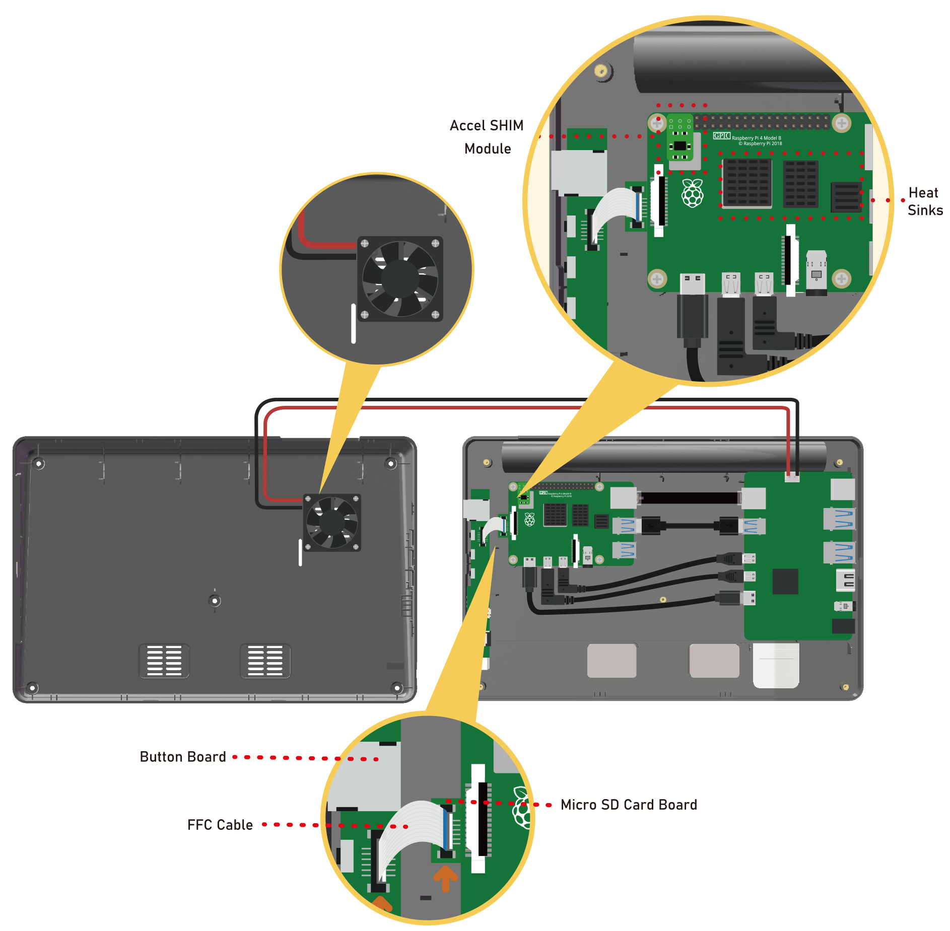
Before inserting the Micro SD card, connect the button-board to the Raspberry Pi using the included FFC cable.
Connect all the cables, and then attach the Raspberry Pi with four of the M2.5x4 screws.
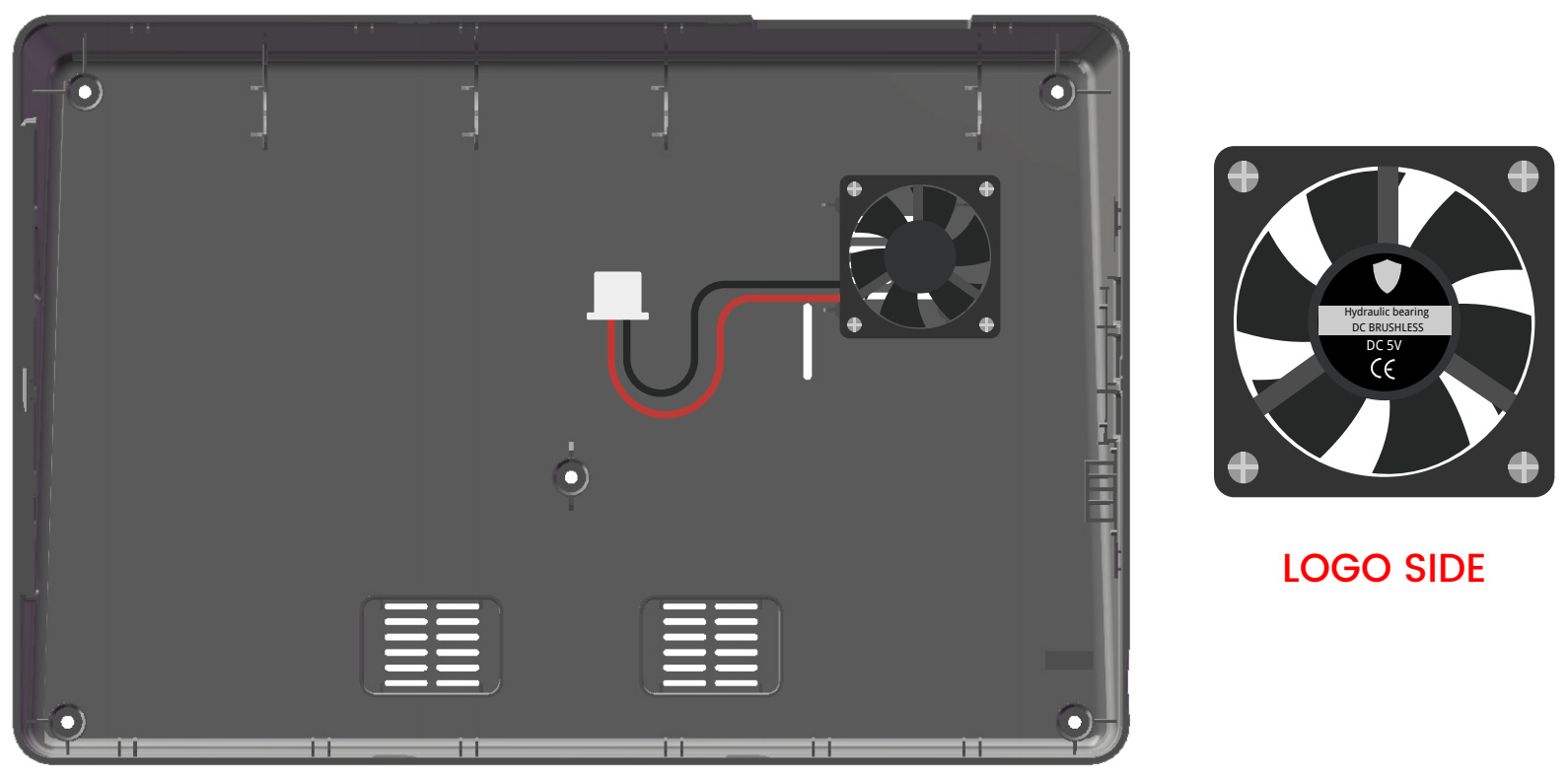
Orient the fan so the logo is facing the exterior vent, then attach the fan with the four PWA1.7X9 screws.
Finally, attach the back cover with five M2.5x4 screws.
You can also follow the video to assemble RasPad 3 step by step.
Detailed Assembly Steps
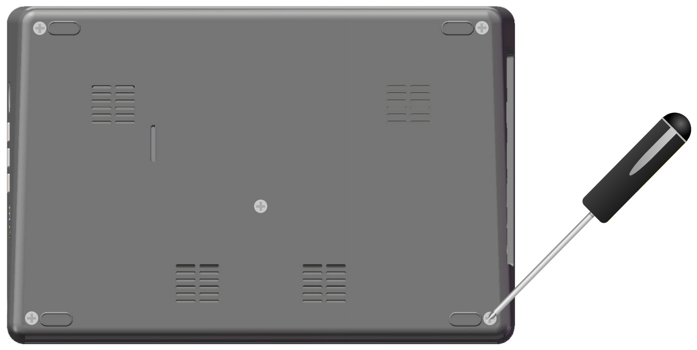
Take out the RasPad and turn it over, unscrew the screws and remove the back cover.
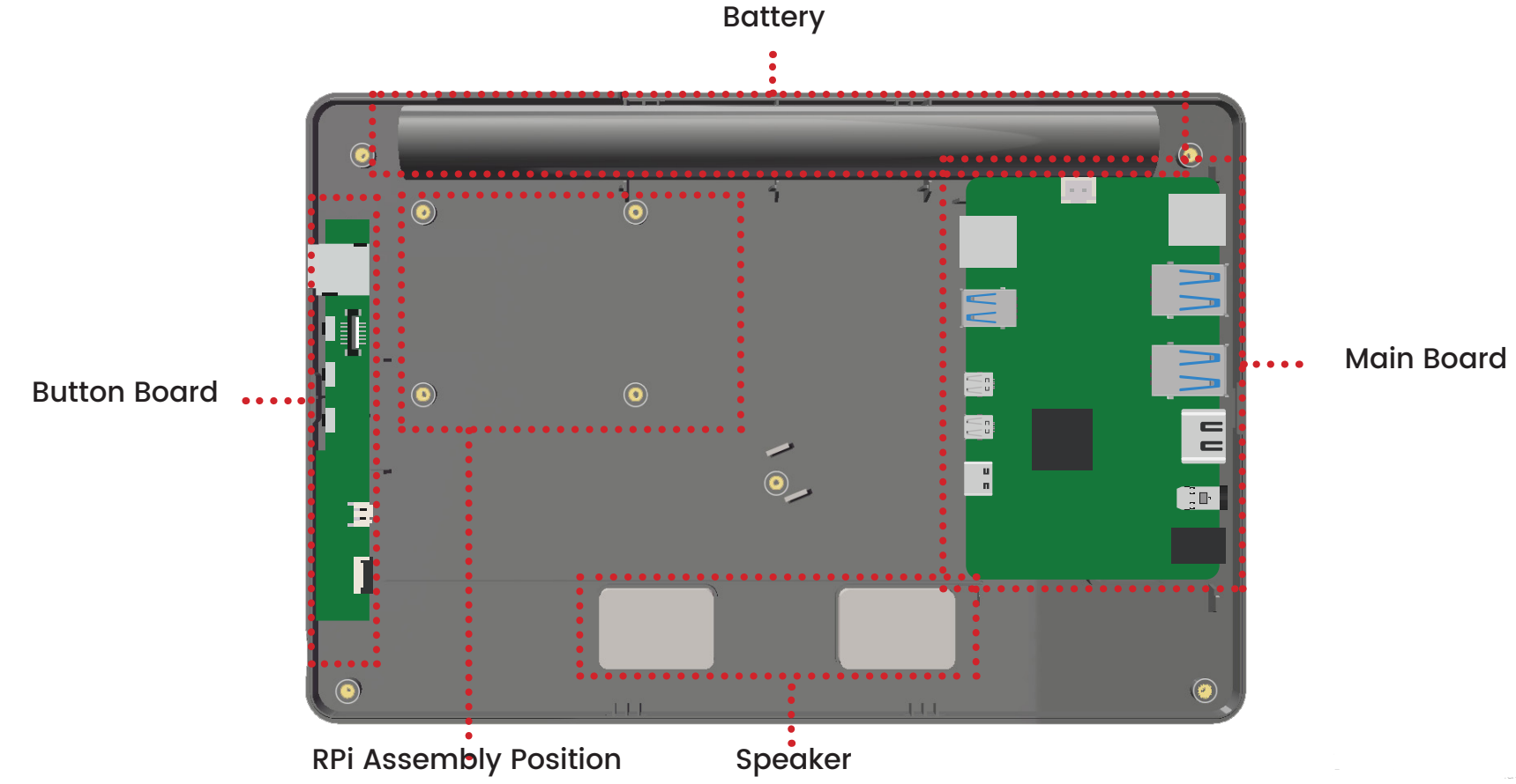
Below is an image of the internal structure of the RasPad.
Note
Avoid pressing on the two speakers during assembly.
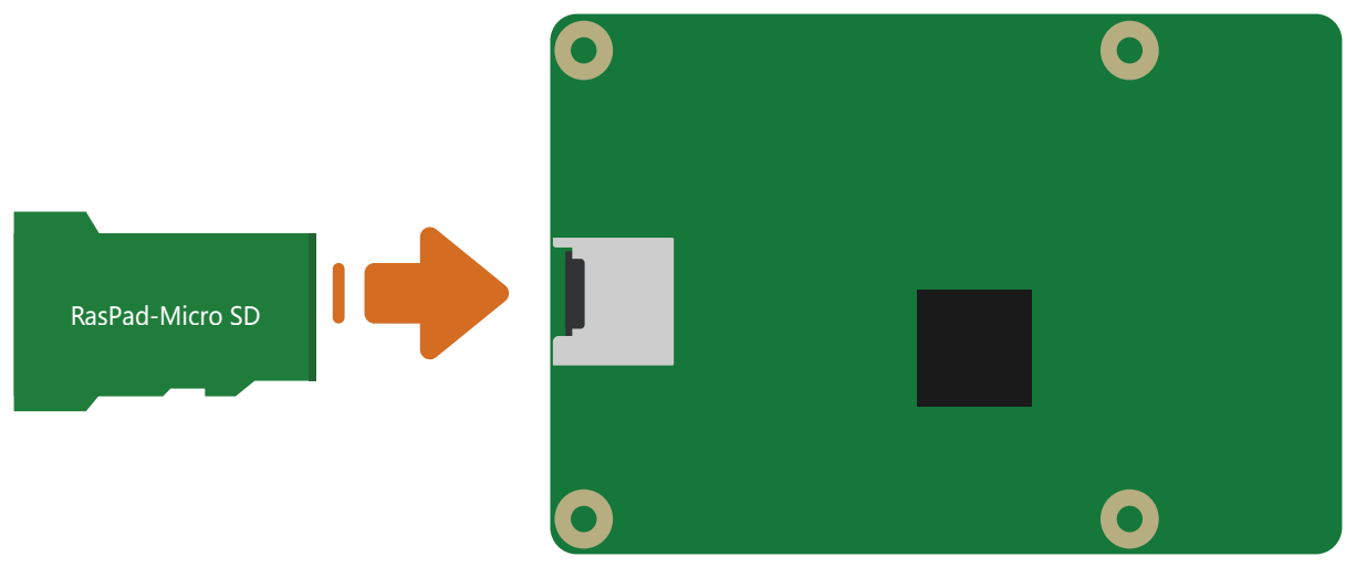
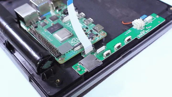
Insert the Micro SD card board into the Raspberry Pi’s Micro SD card slot.
Insert the other end of the FFC cable into the RasPad button board.
Note
This step can be skipped if the Micro SD card board has already been connected to the button board in the RasPad that you received.
Use two fingers to gently pull up the tab on the top of the CSI connector.
Insert the FFC cable, being sure that it is fully inserted and not crooked.
Use your fingers to press it firmly from both sides.
Pull up the tab gently again if it is not attached properly and can’t pull out the FFC forcefully.
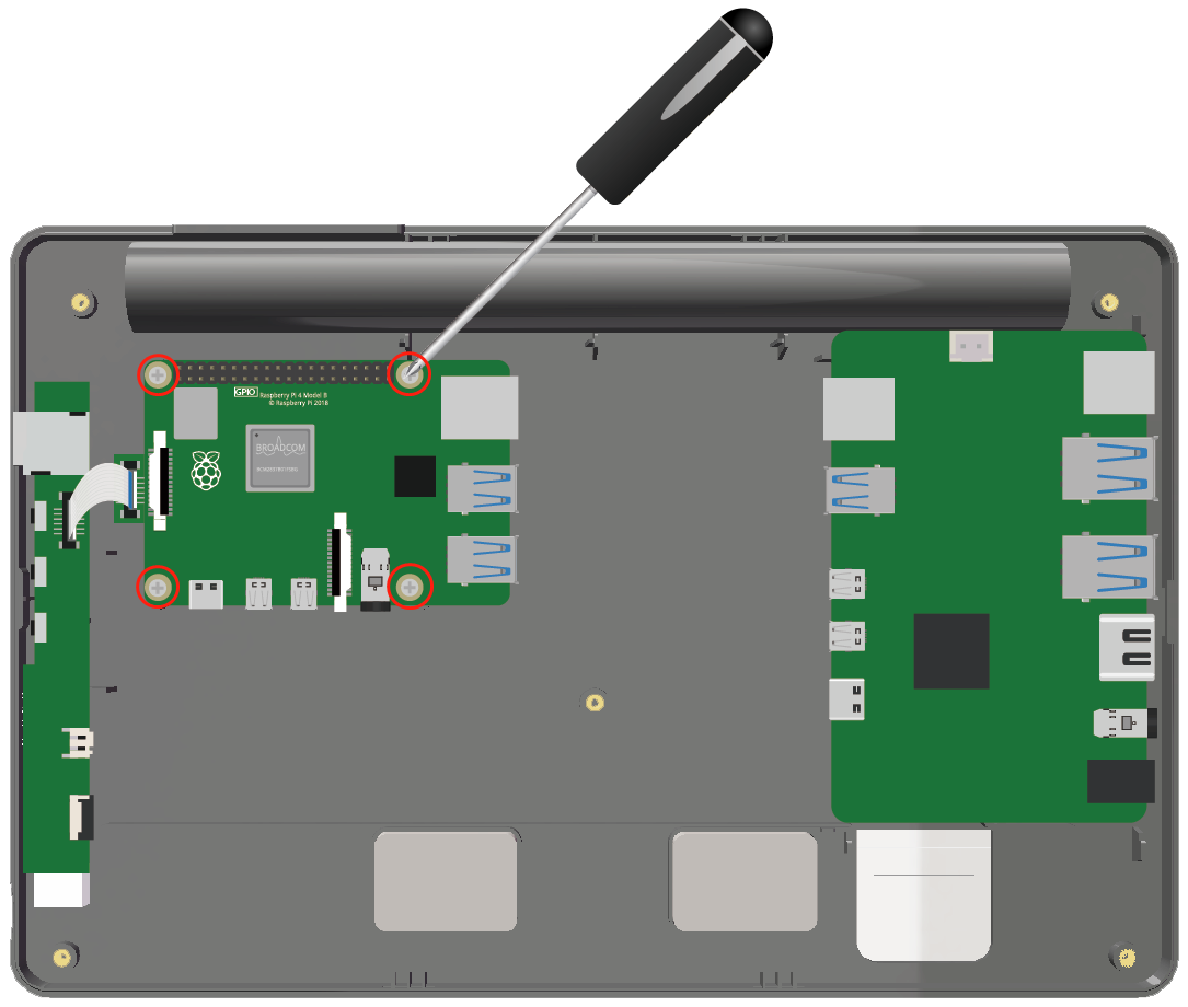
Attach the Raspberry Pi with 4 M2.5x4 screws.
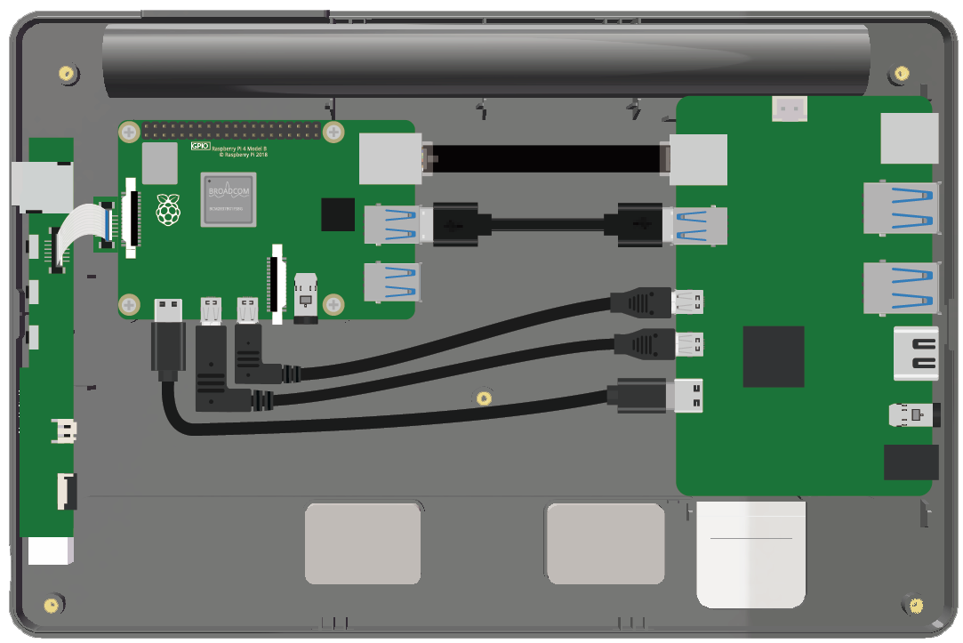
Connect the Ethernet, USB to USB, 2 Mrico HDMI and Type-C cables in order.
Note
It doesn’t matter if you find the direction of two Mrico HDMI cables slightly off, you can just rotate them manually.
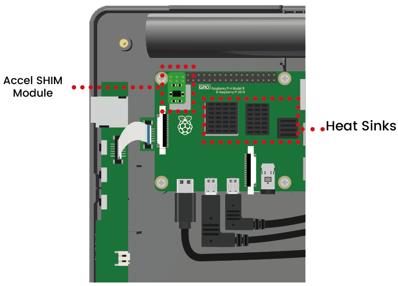
Attach the three heat-sinks to the Raspberry Pi, and insert the Accel SHIM module for the RasPad’s auto-rotate function.
Note
Accel SHIM module has no soldered pins so you need to observe whether the 6 holes are in contact with the Raspberry Pi pins. If not, gently break the Raspberry Pi pins.
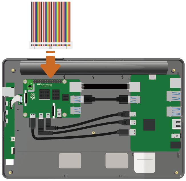
To use the GPIO pins of the Raspberry Pi, connect a 40-pin GPIO ribbon cable to the Raspberry Pi, and route the ribbon cable out the top of the case.
Note
If you don’t need to build the circuit with RasPad, you can skip this step.
Attach the fan onto the back cover with four PWA1.7x9 screws.
Note
The logo faces out towards the exterior vent.
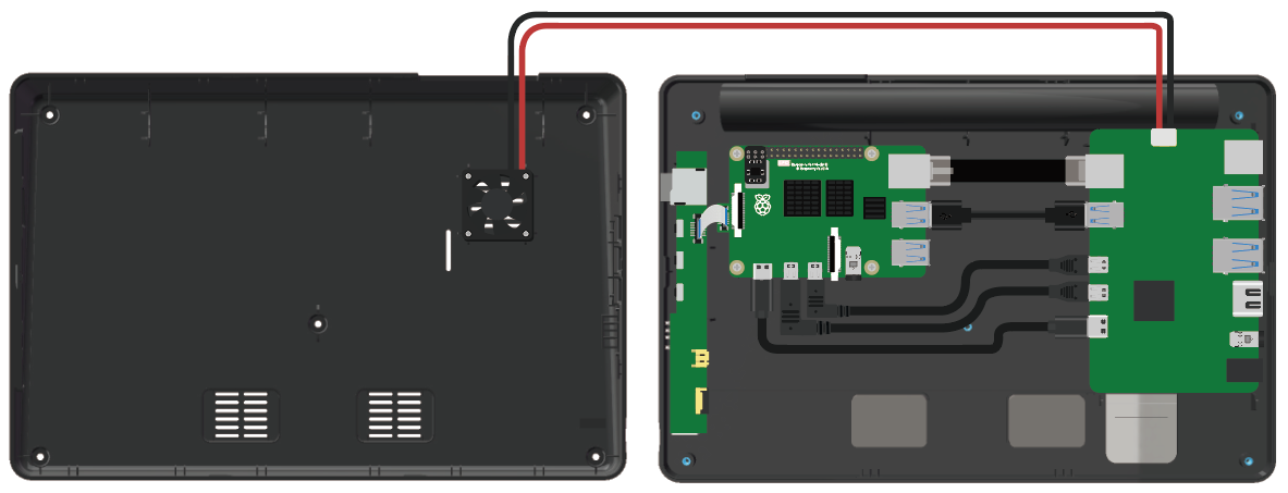
Connect the fan to the Main Board.
Attach the back cover with five M2.5x4 screws.
Note
Do not force the back cover in place. If the enclosure is hard to connect, or the screw-holes do not line up correctly, please check that there are no internal components interfering with the fit before trying to reattach the back cover.